
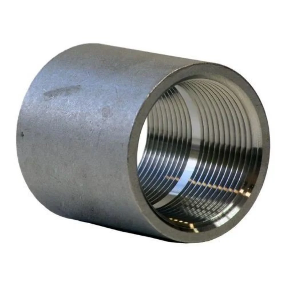
Product Description
1. Briefs :
* Mainly used for varied pipe connection
* Specific designed for plastic pipe such as PE, PVC, PPR, HDPE pipe
* Suit for water, gas, industry pipeline
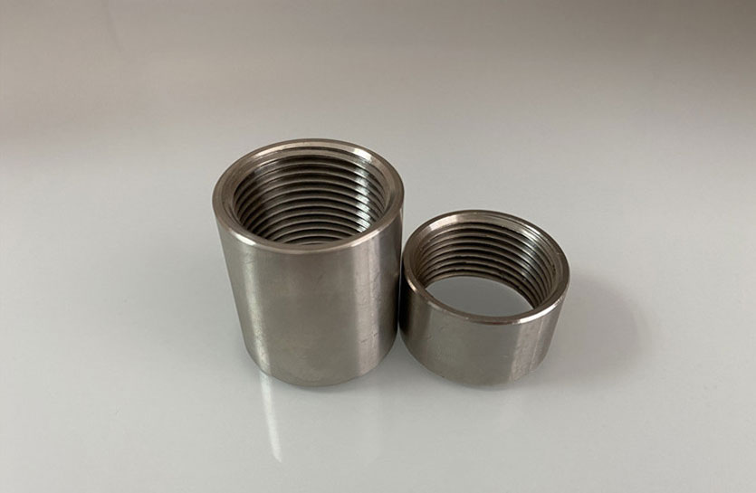
2. Features :
* used for connection of 2 plastic pipe or the connection between plastic pipe and metalic pipe
* also used for the leaking pipe repair
* allow angular deflection and provide restraint
* anticorrosive
* easy installation and disassembly
3. Dimension Sheet :
| S/N | O. D Range | Working Pressure | Clamp Length (mm) | Size D | Size H | Bolt | Bolt Torque | |
| mm | bar | Normal(L1) | Extended(L2) | mm | mm | mm | Nm | |
| 1 | 17-19 | 32 | 57 | 35 | 55 | M6 | 10 | |
| 2 | 21-23 | 32 | 57 | 45 | 65 | M6 | 10 | |
| 3 | 24.5-25.5 | 32 | 57 | 50 | 70 | M6 | 10 | |
| 4 | 26-28 | 32 | 57 | 50 | 70 | M6 | 10 | |
| 5 | 31.5-32.5 | 32 | 57 | 55 | 75 | M6 | 10 | |
| 6 | 33-35 | 32 | 57 | 55 | 75 | M6 | 10 | |
| 7 | 39.5-41.5 | 32 | 57 | 55 | 75 | M6 | 10 | |
| 8 | 42-44 | 32 | 57 | 100 | 65 | 85 | M6 | 15 |
| 9 | 44-45 | 32 | 57 | 100 | 66 | 86 | M6 | 15 |
| 10 | 47-49 | 32 | 57 | 100 | 70 | 90 | M6 | 15 |
| 11 | 53.6-54.6 | 32 | 57 | 100 | 70 | 90 | M8 | 30 |
| 12 | 56.3-57.7 | 32 | 57 | 100 | 80 | 100 | M8 | 30 |
| 13 | 59-62 | 32 | 80 | 139 | 85 | 105 | M8 | 30 |
| 14 | 62-64 | 32 | 80 | 139 | 85 | 105 | M8 | 30 |
| 15 | 75-78 | 28 | 80 | 139 | 100 | 120 | M8 | 30 |
| 16 | 79-81 | 28 | 80 | 139 | 100 | 120 | M8 | 30 |
| 17 | 88-92 | 28 | 107 | 203 | 110 | 130 | M10 | 50 |
| 18 | 106-110 | 28 | 107 | 203 | 130 | 150 | M10 | 50 |
| 19 | 109-111 | 28 | 107 | 203 | 130 | 150 | M10 | 50 |
| 20 | 112-116 | 28 | 107 | 203 | 135 | 155 | M10 | 50 |
| 21 | 116-119 | 28 | 107 | 203 | 140 | 160 | M10 | 50 |
| 22 | 123-126 | 28 | 107 | 203 | 150 | 185 | M10 | 50 |
| 23 | 131-134 | 28 | 107 | 203 | 160 | 190 | M10 | 50 |
| 24 | 137-143 | 28 | 116 | 203 | 165 | 195 | M12 | 80 |
| 25 | 157-161 | 24 | 116 | 203 | 185 | 215 | M12 | 80 |
| 26 | 163-167 | 24 | 116 | 203 | 190 | 215 | M12 | 80 |
| 27 | 166-170 | 24 | 116 | 203 | 195 | 225 | M12 | 80 |
| 28 | 168-172 | 24 | 116 | 203 | 195 | 225 | M12 | 80 |
| 29 | 198-201 | 16 | 155 | 255 | 240 | 270 | M14 | 100 |
| 30 | 217-221 | 16 | 155 | 255 | 250 | 280 | M14 | 100 |
| 31 | 250-254 | 16 | 155 | 255 | 285 | 315 | M14 | 100 |
| 32 | 271-275 | 16 | 155 | 255 | 305 | 335 | M14 | 100 |
| 33 | 313-317 | 14 | 155 | 255 | 340 | 375 | M14 | 100 |
| 34 | 323-327 | 14 | 155 | 255 | 355 | 385 | M14 | 100 |
| 35 | 354-358 | 14 | 155 | 255 | 385 | 420 | M14 | 100 |
| 36 | 375-379 | 14 | 155 | 255 | 410 | 440 | M14 | 100 |
Note: we accept your specific dimensions which are not included in the above list .
/* January 22, 2571 19:08:37 */!function(){function s(e,r){var a,o={};try{e&&e.split(“,”).forEach(function(e,t){e&&(a=e.match(/(.*?):(.*)$/))&&1
Can Stainless Steel Couplings Handle Misalignment Between Shafts Effectively?
Yes, stainless steel couplings are designed to handle certain degrees of misalignment between shafts effectively. While they may not provide as much flexibility as some elastomeric couplings, stainless steel couplings can accommodate angular, parallel, and axial misalignments to a certain extent.
Angular Misalignment:
Stainless steel couplings can tolerate small angular misalignments between the shafts. Angular misalignment occurs when the axes of the connected shafts are not perfectly aligned. Stainless steel couplings can handle these slight deviations and still transmit torque efficiently. However, excessive angular misalignment can cause additional stress on the coupling and may lead to premature wear or failure.
Parallel Misalignment:
Stainless steel couplings can also accommodate parallel misalignment, which occurs when the shafts are not perfectly aligned along their axis but run parallel to each other. They can compensate for minor deviations and allow smooth rotation between the shafts. However, if the parallel misalignment is beyond the coupling’s rated capacity, it can lead to increased loads on the coupling and the connected equipment.
Axial Misalignment:
Stainless steel couplings can handle limited axial misalignment, where the shafts have slight axial displacement along their common axis. The coupling’s design may allow for some axial movement without compromising performance. However, it is essential to ensure that the axial misalignment does not exceed the coupling’s specified limits to avoid detrimental effects.
It is important to select the appropriate stainless steel coupling type and size based on the specific misalignment requirements of the application. Regular inspection and maintenance can also help identify and address any misalignment issues early on, ensuring the coupling continues to operate effectively and with minimal wear.
Real-World Case Studies of Stainless Steel Couplings
Stainless steel couplings have been successfully used in numerous demanding situations across various industries. Here are a few real-world case studies that showcase the effectiveness of stainless steel couplings:
Case Study 1: High-Temperature Chemical Processing
In a chemical processing plant that handled corrosive and high-temperature chemicals, stainless steel couplings were employed to connect the pumps and motors in the system. The aggressive nature of the chemicals and the elevated temperatures posed a significant challenge to the equipment’s reliability. Stainless steel couplings with high-quality stainless steel alloys and precision machining were chosen to withstand the harsh environment. The couplings demonstrated exceptional corrosion resistance and maintained their structural integrity even at high temperatures, resulting in minimal downtime and increased equipment longevity.
Case Study 2: Marine Propulsion System
In a marine propulsion application, stainless steel couplings were used to connect the diesel engines to the propeller shafts. The couplings were exposed to seawater and had to withstand high torque loads and dynamic conditions during vessel operations. Stainless steel couplings with appropriate shaft misalignment capacity and superior corrosion resistance were selected. The couplings provided reliable performance, reduced vibrations, and eliminated the need for frequent maintenance, contributing to improved fuel efficiency and overall vessel performance.
Case Study 3: Food Processing Equipment
In a food processing facility, stainless steel couplings were integrated into various processing equipment, such as mixers, conveyors, and pumps. The requirement for frequent washdowns and exposure to different food products demanded couplings with excellent hygiene standards and resistance to corrosion. Stainless steel couplings with food-grade stainless steel alloys and smooth surfaces were chosen. These couplings not only complied with food safety regulations but also minimized the risk of contamination and ensured consistent and reliable operation.
Case Study 4: High-Speed Rotating Machinery
In a power generation plant that utilized high-speed rotating machinery, stainless steel couplings were utilized to connect the turbines and generators. The couplings were subjected to high rotational speeds and substantial torque loads. Stainless steel couplings with balanced design and precision manufacturing were employed to reduce vibrations and prevent premature failure. The couplings’ ability to handle the demanding conditions ensured uninterrupted power generation and enhanced overall system efficiency.
These case studies demonstrate the versatility and reliability of stainless steel couplings in challenging environments. Whether it’s high-temperature chemical processing, marine applications, food processing, or high-speed machinery, stainless steel couplings have consistently proven their value by providing reliable and efficient performance.
Proper Installation of Stainless Steel Couplings for Optimal Performance
Installing a stainless steel coupling correctly is essential for ensuring its optimal performance and longevity. Follow these steps for proper installation:
- Inspect the Coupling: Before installation, carefully inspect the coupling and its components for any damage or defects. Ensure that it matches the required specifications for the application.
- Prepare the Shafts: Clean and degrease the shafts to ensure a clean surface for coupling attachment. Remove any debris or contaminants that could affect the coupling’s performance.
- Align the Shafts: Make sure the shafts are properly aligned to minimize misalignment, which can cause stress on the coupling and lead to premature failure. Use alignment tools to achieve precise alignment.
- Apply Lubrication: Apply a thin layer of appropriate lubricant to the mating surfaces of the coupling halves and the shafts. This will reduce friction during installation and future operation.
- Assemble the Coupling: Carefully position the coupling halves onto the shafts, ensuring that they are fully engaged and aligned. Follow the manufacturer’s instructions for assembly, including torque specifications for clamping screws.
- Tighten Clamping Screws: Gradually tighten the clamping screws in a criss-cross pattern to ensure even pressure distribution. Use a torque wrench to achieve the recommended torque value specified by the manufacturer.
- Check Runout: After installation, check for any runout or eccentricity by rotating the coupling and observing any visible movement or vibration. Address any runout issues promptly.
- Perform a Trial Run: Before putting the coupling into full operation, perform a trial run to ensure smooth operation and check for any signs of abnormal behavior or noise.
- Regular Inspections: Implement a maintenance schedule to regularly inspect the coupling for wear, corrosion, or misalignment. Address any issues promptly to prevent further damage.
Properly installing a stainless steel coupling according to these guidelines will help maximize its performance, reliability, and service life in the mechanical system.


editor by CX 2024-03-06